Microcontroller Design Overview:
Figure 1: MCU Design
The way that Nordic MCU used to work is through RTOS. That means that every time the MCU wants to sample voltage using ADC, it starts a RTOS thread in the system. This system would work for low-frequency sampling. However, for the higher frequency sampling of this project (10kHz), it is not feasible. Simply put, it is not desirable to start putting a RTOS thread at 10000 times per second, with all the jitter that the system produces.
The way to solve this problem is to use a hardware timer and direct memory access. Instead of running through RTOS, the ADC is pulled out of RTOS and connected to a hardware timer, in this case TIMER1 on nRF5340. A more advanced configuration of ADC, called successive approximation analog-to-digital converter (SAADC), is used for ADC sampling. The timer is connected to SAADC through a distributed programmable peripheral interconnect (DPPI), an interface that connects different hardware components without involving the CPU.
TIMER2 is configured to generate a compare event every 100 µs (corresponding to a 10 kHz sample rate). and this event is published onto DPPI, which then triggers the SAADC to collect a sample. Each sample task produces exactly one ADC conversion, and the resulting 12-bit value is written directly into a direct memory access buffer. The SAADC continues receiving these SAMPLE triggers until a buffer accumulates 80 samples; at that point the SAADC emits a signal to end the task. The end of this event activates two independent paths: first, through DPPI, it automatically resets the SAADC to begin filling the next buffer without CPU involvement; second, it raises an interrupt that invokes the SAADC event handler. In this handler, it captures a timestamp, moves the completed buffer into a staging array, and schedules a Bluetooth LE work item. The overall framework is shown in the diagram below:
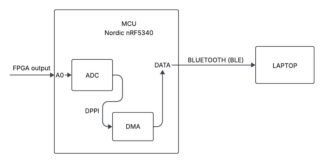
Figure 2: Block diagram overview
The sampling engine never pauses during this processing. Hardware continues sampling using the other buffer, so BLE congestion or CPU load cannot interfere with timing. The routing therefore establishes a clean closed loop: TIMER2 COMPARE -> SAADC SAMPLE -> DMA -> SAADC END -> SAADC START -> await next TIMER trigger.
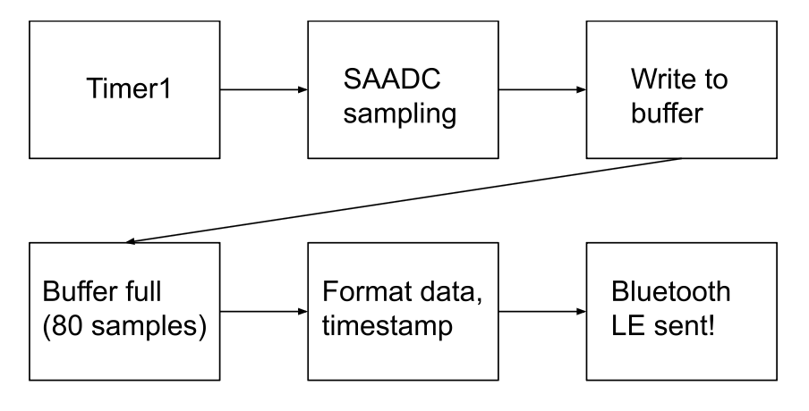
Figure 3: Flowchart of DMA to BLE
The Bluetooth work handler serves as the non-interrupt context for transmitting a completed ADC buffer over Bluetooth. When the SAADC interrupt indicates that a DMA buffer has been filled, the samples and their timestamp are copied into a staging area, and this work handler is scheduled to run asynchronously. Next, the handler constructs the payload: it writes a 4-byte little-endian timestamp at the beginning, then serializes each 16-bit ADC sample into two bytes, forming a contiguous notification packet. Each packet is 80 samples. So, since it is 10000 samples/sec, there are 125 packets that are being sent per second. With the payload prepared, the handler attempts to send the buffer through the Generic ATTribute Profile (GATT) notify characteristic, which defines the way the BLE devices communicate with each other. All the features that need to be communicated over BLE are stored in the GATT profile. The ADC sample is held in a data channel, which is referred to as a characteristic in the BLE domain. If the BLE stack is temporarily unable to accept more data, most commonly because the queue is full. In that case, the handler increments a retry counter and either reschedules itself after a delay (allowing the BLE controller time to clear its buffers) or, if the retry limit (5 in this case) is exceeded, drops the buffer to avoid blocking subsequent samples. This retry mechanism prevents BLE congestion from ever halting the acquisition pipeline. This is now being tested on a 1kHz sine wave:
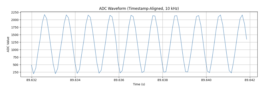
Figure 4: Output signal of ADC
From 89.642 to 89.632, that is 0.01 second interval. Since it is a 1kHz signal sampled at 10kHz, that is 1000 cycles/second. Therefore, for a 0.01 second window visualization, it is expected to have 10 cycles, and there are just 10 peaks shown in the plot above. Therefore, it proves that the ADC + Bluetooth LE framework for the microcontroller is working properly! Unfortunately, the BLE does drop some packets (~10%). However, considering the goal of USDA ecologists is to sample a 1kHz signal, sampling it at 10kHz with 10% does not really affect signal integrity,